


Read more

Electricity – Derived a word electron- means amber
1. Introduction
Physical
phenomena associated with the presence and flow of electric charge is known as
electricity. Electricity and electrical phenomenon have a lot of applications
in our day to day life and they also gives a wide variety of well-known
effects, such as lightning, static electricity, electromagnetic induction and
the flow of electrical current.
विद्युत आवेश की उपस्थिति और प्रवाह से जुड़ी भौतिक घटनाओं को विद्युत के रूप में जाना जाता है। हमारे दैनिक जीवन में विद्युत और विद्युत परिघटनाओं के बहुत सारे अनुप्रयोग हैं और वे खास प्रभावों की एक विस्तृत विविधता भी देते हैं जैसे विद्युत, स्थैतिक विद्युत, विद्युत चुम्बकीय प्रेरण और विद्युत का प्रवाह।
विद्युत कई प्रकार
की
होती
है
:
- Electricity
occurs due to several types :
- Electric
charge: a
property of some subatomic particles, which determines their electromagnetic
interactions.
- Electric
current: a
movement or flow of electrically charged particles, typically measured in
amperes.
- Electric
field: an
especially simple type of electromagnetic field produced by an electric
charge even when it is not moving (i.e., there is no electric current).
The electric field produces a force on other charges in its vicinity.
Moving charges additionally produce a magnetic field.
- Electric
potential: the
capacity of an electric field to do work on an electric charge, typically
measured in volts.
- In this chapter we will study
about electricity.
There are two types of Electricity
1.
Static Electricity - Static Electricity is
made by rubbing together two or more
objects and making friction.
2.
Current Electricity - Current electricity is
the flow of electric charge across an electrical field.
Static Electricity
Static
electricity is when electrical charges build up on the surface of a material.
It is usually caused by rubbing materials together. The result of a build-up of
static electricity is that objects may be attracted to each other or may even
cause a spark to jump from one to the other. For Example rub a baloon on a wool
and hold it up to the wall.
Before rubbing,
like all materials, the balloons and the wool sweater have a neutral charge.
This is because they each have an equal number of positively charged subatomic
particles (protons) and negatively charged subatomic particles (electrons).
When you rub the balloon with the wool sweater, electrons are transferred from
the wool to the rubber because of differences in the attraction of the two materials
for electrons. The balloon becomes negatively charged because it gains
electrons from the wool, and the wool becomes positively charged because it
loses electrons.
Current
Electricity
Current is the
rate of flow of electrons. It is produced by moving electrons and it is
measured in amperes. Unlike static electricity, current electricity must flow
through a conductor, usually copper wire. Current with electricity is just like
current when you think of a river. The river flows from one spot to another,
and the speed it moves is the speed of the current. With electricity, current
is a measure of the amount of energy transferred over a period of time. That
energy is called a flow of electrons. One of the results of current is the
heating of the conductor. When an electric stove heats up, it's because of the
flow of current.
There are
different sources of current electricity including the chemical reactions
taking place in a battery. The most common source is the generator. A simple
generator produces electricity when a coil of copper turns inside a magnetic
field. In a power plant, electromagnets spinning inside many coils of copper
wire generate vast quantities of current electricity.
There are two
main kinds of electric current.
1.Direct (DC) and
2.Alternating (AC).
It's easy to remember.
Direct current is like the energy you get from a battery. Alternating current
is like the plugs in the wall. The big difference between the two is that DC is
a flow of energy while AC can turn on and off. AC reverses the direction of the
electrons.
Electric charge: -
- We know that all matter (saolid , liquid
and gas) is comprised of atoms, and all atoms consists of positively
charged particles and negative charged particles.
- Electric charge is a fundamental property
like mass; length etc. associated with elementary particles for example
electron, proton and many more.
- Electric charge is the property
responsible for electric forces which acts between nucleus and electron to
bind the atom together.
- Charges are of two kinds
1. negative charge
2. positive charge
- Electrons are negatively charged particles
and protons, of which nucleus is made of, are positively charged
particles. Actually nucleus is made of protons and neutrons but neutrons
are uncharged particles.
- Electric force between two electrons is
same as electric force between two protons kept at same distance apart
i.e., both set repel each other but electric force between an electron and
proton placed at same distance apart is not repulsive but attractive in
nature
- All free charges are integral multiples of
a unit of charge e,
where e = -1.602 ×
10 -19 C i. e., charge on an electron or proton.
- Thus charge q on a body is always denoted
by
q = ne
where n = any integer positive or negative - Charge on electron and proton –
e = -1.602 × 10 -19
C SI unit = 6.25×
10 -18
p = +1.602 × 10 -19 c
e = -4.8 × 10 -10
e.s.u
p = +4.8 × 10 -10 e.s.u CGS Unit
·
Value
of charge e and
p = equal (1.602 × 10 -19 4.8 × 10 -10)
·
Nature
of e and p =
opposite , ( - , + )
·
electronic
charge (e)
e = 0 –
neutron
e = -1
- electron
e = +1 - proton
·
mass
n = 1
e = 0 (1/1840)
p = 1
Unit of electric Charge
- charge is denoted by q.
- Charge on a system can be measured by
comparing it with the charge on a standard body.
- SI unit of charge is Coulomb written as C.
- CGS unit of charge is electrostatic unit
written as e.s.u.
- 1 Coulomb is the charge flowing through
the wire in 1 second if the electric current in it is 1A.
- It is sclar quantity.
- It is additive in nature .
- It is always conserved in nature.
- It is quantization. ( q = ±ne
) where n = 1,2,3,….. Q = ±e
, ±2e, ±3e…….
Electric field ( विधुतीय क्षेत्र )–
The area around a positive charge so far as the effect of that
charge is on, is called electric field.
किसी धन आवेश के चारो ओर का वह क्षेत्र जहां तक उस आवेश का प्रभाव परता है, विधुतीय क्षेत्र कहलाता है।

Electric intensity ( विधुतीय तीव्रता
)
The force acting on a unit positive charge located in an electric field is called electric intensity. It is denoted by E.
विधुतीय क्षेत्र
में स्थित
एकांक धनावेश पर
लगने वाला
बल को
विधुतीय तीव्रता कहा जाता
है । इसे E द्वारा निरूपित किया जाता है।


Electric Line of Force (विधुतीय बल रेखा) –
The electric line of force in an electric field is the imaginary line on which the free positive charge is free to move. (विधुतीय क्षेत्र में विधुतीय बल रेखा वह काल्पनिक रेखा है जिस पर सवतंत्र धनावेश चलने के लिए स्वतंत्र है।)

· The
body in which electric charge carries (free electrons) are found to be mobile
and due to which an electric current is generated then this type of body is
called good conductor or conductor.
·
All
metallic bodies, acids, human body etc. are good conductor of electricity.
· The best conductors are mettalicbodies like – silver, copper,iron etc.
· Silver and copper are the two well known metals which have thebest electrical conductivity.
· In all metallic bodies only free electrons are charge carries due to which electric current generates.
2. Non- conductor/insulator/bad conductor :-
·
The
body which does not have mobile charge carries are called bad conductor.
·
Sometimes
in bad conductor also immobile charge carries are activated to become free in a
zig- zag way but not regularly like in wet rod of wood , thus it acts like a
good conductor is called insulator.
·
Wood
, rubber mica etc. are examples of bad conductors but asbestos , ebonite etc.
are examples of insulator.
3. Semi – conductor :-
·
Super conductors are metals and compounds whose resistivity
aproches zero below a certain temperature ( critical temperature ) is
phenomenon is called superconductivity.
· For ex - substance crirical temperature
zinc 0.88
Aliminum 1.19
Tin 3.72
Mercury 4.15
Coulomb’s law
Coulomb's Law statement
In 1785 the French physicist Charles
Augustin Coulomb measured the electric force between small
charged spheres using a torsion balance. He then formulated his observations in
the form of Coulomb's Law. Coulomb's Law is an electrical analog of Newton's
Universal Law of Gravitation. It states that
The force of attraction or repulsion between two
stationary point charges is
(i) directly proportional to the product of the
magnitude of two charges.
(ii) inversely proportional to the square of the distance between them.
This force acts along the line joining the two charges.
To explain above statement consider the figure given
below

Coulomb's Law
Above figure consists of two point charges q1q1 and q2q2.
These two charges are separated by a distance r. Then according to Coulomb's
Law the force FF of
attraction or repulsion between them is,
F∝q1q2 and F∝1/r2
Therefore,
F ∝ q1q2/r2 (1)
or,
F=kq1q2/r2
where, k is the constant of proportionality. The value
of k depends on the nature of the
medium between two charges and the system of units we choose to measure F, q1, q2 and r.
In SI units system, when two charges are in vacuum or
air
K = 1/4πε0
where ε0 is absolute
permittivity of free space. Value of this constant in vacuum
is 8.85×10⁻¹²C2/Nm2.
If we put the value of ε0 in above equation for kk we find
k=1/4πε0 =1/4×π×8.85×10−12C2/Nm2=9×109Nm2C−2k=14πε0=14×π×8.85×10−12C2/Nm2=9×109Nm2C−2
So, from above equation (1) the force between two
charges located in air or vacuum is given by,
F=14πε0q1q2r2=9×10⁹×q1q2/r2F=1/4πε0q1q2r2=9×109×q1q2r2 (in Newton)
Now if the charges are in a medium (glass, water etc.) other then air and vacuum then electric force between these two charges is F=1/4πε0q1q2/r2
where, ε is a constant and is the the permittivity of
the medium in which charges are present. Since the value of εε depends on the medium, the magnitude of force
on a charge also depends on the medium.
NOTE:-
- The direction of the force is along the
line joining two charges. It can be inward or outward depending on
attraction or repulsion between the charges.
- Coulomb's Law of electrostatics holds for
two or more point charges ate rest.
- SI unit of permittivity is C2/Nm2. It can also be expressed as farad per meter (F/m).
The difference in electric potential between
two points in electric field is termed as potential difference.
Thus, the potential difference between two
points in an electric field (circuit) is defined as the amount of workdone in
moving a unit charge from one point to another .
If W joules of work is done to move Q coulomb
of electric charge from one point to the otherpoint, then the potential difference V
between the two point is expressed as :
Where V = Ptential difference
W = work done
Q = quantityof charge moved.
If 1 joule
of work is done to move 1 coulomb of electric charge fromone point to other
point,the potential difference between these points is
said to be 1 volt.
Mathematically,
1 volt =
1joule / 1coulomb
or Volt = joule × (coulomb) -1
so 1V = 1JC-1
- It is mesured by volt meter and always connected in parallel across the two points .


Electric current and electrical circuits
-
- Consider two metallic
conducting balls charged at different potential are hanged using a
non-conducting insulating wires .Since air is an insulator ,no charge
transfer takes place
- Now if we join both the
metallic wire using a conducting metallic wire then charge will flow from
metallic ball at higher potential to the one at lower potential.
- This flow of charge will stop
when the two balls would be at the same potentials.
- If somehow we could maintain
the potential between the metallic balls through a cell or battery, we
will get constant flow of the charge in metallic wire, connecting the two
conducting balls
- This flow of charge in metallic
wire due to the potential difference between two conductors used is called
electric current.
- So, Electric current is
expressed by the amount of charge flowing through a particular area in
unit time(1 second).
- In other words, it is the rate
of flow of electric charges (electrons) in a conductor (for example copper
or metallic wire).
- If a net charge Q, flows across
any cross-section of a conductor in time t, then the current I, through
the cross-section is
I = Q/t
The S.I. unit of electric current is Ampere, denoted by (A). - if in the above formula Q is
1coulomb and t is 1 second then, I = Q/T= 1A
- When 1 Coulomb of charge flows
through a cross-section of conductor in 1 second then current flowing
through the conductor is said to be 1 Ampere.
- A smallest unit of electric
current ‘milliampere’(mA)
1milliampere = 1/1000 ampere
1 mA= 1/1000A
=10-3 A
- Current is measured by an
instrument called ammeter. It is always connected in series in a circuit
through which the current is to be measured.
- A continuous and closed path of
an electric current is called an electric circuit. For example figure
given below shows a typical electric circuit comprising a cell, an
electric bulb, an ammeter A and a plug key K.

Note that the electric current flows in the circuit from the positive terminal of the cell to the negative terminal of the cell through the bulb and ammeter - The conventional direction of
electric current is from positive terminal of the cell to the negative
terminal through the outer circuit.
- we can say that conventional direction of
electric current is in the direction of the flow of positive charged
carriers.
- We already know that electric
circuit is a continuous path consisting of cell (or a battery), a plug
key, electrical component(s), and connecting wires.
- Electric circuits can be
represented conveniently through a circuit diagram.
- A diagram which indicates how
different components in a circuit have to be connected by using symbols
for different electric components is called a circuit diagram.
- Table given below shows symbols
used to represent some of the most commonly used electrical components

Ohm's Law
- Ohm's
law is the relation between the potential difference applied to the ends
of the conductor and current flowing through the conductor. This law was
expressed by George Simon Ohm in 1826.
- Statement
of Ohm's Law
If the physical state of the conductor (Temperature and mechanical strain etc.) remains unchanged, then current flowing through a conductor is always directly proportional to the potential difference across the two ends of the conductor. in other words -----
At constant temperature , the current flowing through a conductor is directly proportional to potential difference its ends. - mathematically
V ∝ I
or
V=IR
where constant of proportionality R is called the electric resistance or simply resistance of the conductor. - Value
of resistance depends upon the nature, dimension and physically dimensions
of the conductor.
- From
Ohm's Law
-
Thus electric resistance is the ratio of potential difference across the
two ends of conductor and amount of current flowing through the conductor.
- If
a graph is drawn between the potential difference readings (V) and the
corresponding current value (I), then the graph is found to be a straight
line passing through the origin as shown below in the figure

- From
graph we see that these two quantities V and I are directly proportional
to one another.
- Also from this graph we see that current (I) increases with the potential difference (V) but their ratio V/I remain constant and this constant quantity. Resistance
- The poperty of a conductor due to which it posses the flow of current through it is called resistance.
- Electric
resistance of a conductor is the obstruction offered by the conductor to
the flow of the current through it.
- Resistance (R) = Potential difference/ Current OR R = V/I
- SI
unit of resistance is Ohm (Ω) where 1 Ohm=1 volt/1 Ampere or 1Ω=1VA-1.
Bigger units of resistance are Kilo-Ohm and Mega-Ohm
1KΩ=103Ω
1MΩ=106Ω - Omh(Ω) - 1 ohm is the resistance of a conductor such that when a potential difference of 1 volt is applied to its ends , a current of 1 ampere flows through it .
- The
resistance of the conductor depends
- on its length,
- on its area of cross-section
- on the nature of its material
- on the temperature of the conductor .
- We already know that electric
circuit is a continuous path consisting of cell (or a battery), a plug
key, electrical component(s), and connecting wires.
- Consider two metallic
conducting balls charged at different potential are hanged using a
non-conducting insulating wires .Since air is an insulator ,no charge
transfer takes place


1. On its length - The resistance of the conductor is directly proportional to the length of the conductor . thus resistance increase with rise of temperature of the conductor and vice - versa .
or R ∝ l
2.On its area of cross - section -- The resistance of a conductor is inversely proportional to the area of its cross section. Thus resistance of the conductor decrease with increase in the area of cross- section and vice - versa.
or R ∝ l/A
3.On the nature of its material -- Electrical resistance of a conductor also depends on the nature of the material of which it is made. For example a copper wire has less resistance then a nichrome wire of same length and area of cross-section.
or R ∝ l or R ∝ l/A
4.On the temperature of the conductor - - The resistance of the conductor increase on increasing temperature, and vice - vera . but in semi conductor the resistance decrease with rise (increase ) in the temperature.
From above figure we can see that straight
line graph means that ratio V/I is constant . This constant ratio is called
resistance R of the conductor. Resistance may be ohmic or non-ohmic.
(a) Resistors (or devices) for which potential
difference and current graph is a straight line are called ohmic resistors.
Their resistance remains same throughout their operation.

Examples are metallic conductors.
(b) Resistors (or devices) for which potential difference-current graph is not a straight line are called non-ohmic resistors.

Examples are liquid electrolytes, diodes etc.
Specific Resistance -
- It is also known as resistivity.
- The resistivity of a substance is numerically equal to thr resistance of a rod of that substance which is 1 metre long and 1 square metre in cross - section.
- Resistivity = resistance × area of cross section / length or ρ=R ×A /l Where:
R is the electrical resistance of a uniform specimen of the material measured in ohms
l is the length of the piece of material measured in metres, m
A is the cross-sectional area of the specimen measured in square metres, m^2 The SI unit of electrical resistivity is the ohm⋅metre (Ω⋅m). It is commonly represented by the Greek letter ρ, rho.
Although the SI resistivity unit, the ohms metre is generally used, sometimes figures will be seen described in terms of ohms centimetres, Ω⋅cm.
Material resistivity levels
Materials are put into different categories according to their level or resistivity. A summary is given in the table below.
RESISTIVITY REGIONS FOR DIFFERENT CATEGORIES OF MATERIALS
MATERIAL TYPE
RESISTIVITY REGION
Electrolytes
Variable*
Insulators
~10^16
Metals
~10^-8
Semiconductors
Variable*
Superconductors
0
1.Series grouping combination
2.parallel grouping combination
1.Series grouping combination - When two or more resistances are connected end to end consecutively , they are said to be connected in series.


Effect of Electric Current (विद्युत धारा के प्रभाव)
1.Heating effect of current (विद्युत धारा के उष्मीय (तापीय ) प्रभाव)
2.Chemical effect of current (विद्युत धारा के रासायनिक प्रभाव)
3.Magnetic effect of current (विद्युत धारा के चुम्बकीय प्रभाव)
1.Heating effect of current :-
Quantity of heat produced (उत्पन्न ऊष्मा का परिमाण )

Joule's law of thermal effect (तापीय प्रभाव के जूल का नियम )
From R resistance to t time electric current I flowing , the value produced in resistance H = I2Rt is called Joule's law of thermal effect of electric current.
(R प्रतिरोध से t समय तक I विद्युत् धारा प्रवाहित होने से प्रतिरोध में उत्पन्न मान H =I2Rt को विद्युत् धरा के तापीय प्रभाव के जूल का नियम कहा जाता है। )
1. First law /law of Electric current - In a given conductor in a given time the quantity of heat produced is proportional to square of the steady current through it.
(किसी चालक में दिए समय में उत्पन्न उष्मा के मात्रा उससे प्रवाहित विद्युत् धारा के परिमाण के वर्ग के समानुपाती होती है। )
2. Second law / Law of Resistance - For a given current and in a given time the quantity of heat produced in a conductor is proportional to the electrical resistance of the conductor.(किसी चालक में प्रवाहित होने वाली नियत विद्युत् धारा के कारण दिए समय मे उत्पन्न उष्मा मात्रा चालक के विद्युत् प्रतिरोध के समानुपाती होती है। )
3. Third Law / Law of time - In given conductor the quantity of heat produced due to a given current is proportional to the time for which the current passes through it .(किसी चालक से प्रवाहित होने वाली नियत विद्युत् धारा के कारण चालक में उत्पन्न उष्मा की मात्रा जितने समय तक धारा प्रवाहित होती है उस समय के समानुपाती होती है। )
Electric Power ( विद्युत् शक्ति )
- The time rate of doing work is called power
- It is denoted by P.
- It is Scalar quantity.
- The SI unit of power = joule / second
- The unit of j/s is called watt (W), so the SI unit of power is watt (W).
- When a body works at the rate of 1j per second , then its power is 1 watt (W).
- Generally , bigger unit called kilowatt (kW) is used .
Horse power -
- Other unit of power is Horse power , denoted by hp.
- Power of machine is measured in hp.
- Generally , power of man = 0.05hp to 1 hp
Commercial Unit of Electric Energy
- The kilowatt-hour (SI symbol: kW⋅h or kW h; commonly written as kWh) is a unit of energy equal to 3600 kilojoules (3.6 megajoules).
- kilowatt-hour (kWh) is also called Board of Trade Unit (B.O.T.U).
- The kilowatt-hour is commonly used as a billing unit for energy delivered to consumers by electric utilities.
- If an electrical appliance with a capacity of 1000 W is used for 1 hour, then the electrical energy consumed by the appliance will be 1kWh or 1 unit. (यदि 1000 W के सामथ्य वाले विद्युत् उपकरण को 1 घंटा तक प्रयुक्त किया जाये तब उपरण द्वारा उपयुक्त (consumed ) विद्युत् ऊर्जा 1kWh या 1 यूनिट होगी। )
Application of Heating Effect of Electric Current (विद्युत धारा के ताप प्रभाव का अनुप्रयोग)
1.Electric bulb (बिजली के बल्ब)
2.Tube light (टूयूब लाइट )
3. Electric heater (विद्युत् हीटर )
1.Electric bulb (बिजली के बल्ब) : -

- The Electric bulb Was firstly invented by Thomas AlvaEdison.
- The bulb is evaculated (vaccum created ).
- Filament of electric bulb is made up of tungsten as -
- The metal are using making the filament of the bulb which have melting point and high atomic weight .
- It does not Oxidesd readly at heigh temperature.
- It has heigh melting melting(3380 degree celcius).
- The bulb bare filled with chemically inactive gases like nitrogen, argon to prolong the life of filament.
- At high temperature tungsten vapourise and sometimes the inside walls of the bulb is blackened which is called blackering.
- On passing the electric current normally the bulb's filament acquires the temperature from 1500 to 2500 degree celcius.
- In ordinary bulbs only 5% to 10%electrical energy is converted in to light energy, whilethe rest is destroyed in the form of thermal energy.

Material Used Inside the Tube Light
The materials used to build a tube light are given below.
- Filament coils as electrodes
- Phosphor coated glass bulb
- Mercury drop
- Inert gases (argon)
- Electrode shield
- End cap

Auxiliary Electrical Components along with Tube Light
The tube light does not work directly on power supply. It needs some auxiliary components to work. They are-
- Ballast: It may be electromagnetic ballast or electronic ballast. An electronic ballast is a device which controls the starting voltage and the operating currents of lighting devices.
- Starter: The starter is a small neon glow up lamp that contains a fixed contact, a bimetallic strip and a small capacitor.
- Capacitors are one of three fundamental electronic components that form the foundation of a circuit – along with resistors and inductors. A capacitor in an electrical circuit behaves as a charge storage device. It holds the electric charge when we apply a voltage across it, and it gives up the stored charge to the circuit as when required.

Working Principle of Tube Light
- When the switch is ON, full voltage will come across the tube light through ballast and fluorescent lamp starter. No discharge happens initially i.e. no lumen output from the lamp.
- At that full voltage first the glow discharge is established in the starter. This is because the electrodes gap in the neon bulb of starter is much lesser than that of inside the fluorescent lamp.
- Then gas inside the starter gets ionized due to this full voltage and heats the bimetallic strip that is caused to be bent to connect to the fixed contact. Current starts flowing through the starter. Although the ionization potential of the neon is little bit more than that of the argon still due to small electrode gap high voltage gradient appears in the neon bulb and hence glow discharge is started first in starter.
- As voltage gets reduced due to the current causing a voltage drop across the inductor, the strip cools and breaks away from the fixed contact. At that moment a large L di/dt voltage surge comes across the inductor at the time of breaking.
- This high valued surge comes across the tube light electrodes and strike penning mixture (mixture argon gas and mercury vapor).
- Gas discharge process continues and current gets path to flow through the tube light gas only due to low resistance as compared to resistance of starter.
- The discharge of mercury atoms produces ultra violet radiation which in turn excites the phosphor powder coating to radiate visible light.
- Starter gets inactive during operation of tube light.

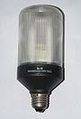
The compact fluorescent light bulb or lamp is a type of fluorescent lamp generally designed as a replacement for incandescent or halogen lamps. There are two major types of compact fluorescent lamp, screw-in and plug-in.
Screw in lamps are self-ballasted and can generally be placed in an existing screw socket without any additional equipment, plug-in bulbs require a ballast and a socket that corresponds to their specific base configuration. These are also sometimes referred to as integrated (screw base) and non-integrated (plug base).
Both come in a wide variety of wattages, sizes, color temperatures, and base types, and they are known primarily for their efficiency, long life, low cost, and ease of upgrading.
Where did they come from?
Although compact fluorescent lamps are considered to be a fairly recent technology, this bulb type was actually over 100 years in the making. Circline and U-bent bulbs were both created to reduce the overall length of fluorescent bulbs and were precursors to the CFL as it is known today.
The modern CFL was invented by Edward Hammer, an engineer at General Electric, but was not produced at the time due to high production costs. In 1980, Philips became the first manufacturer to mass-produce a compact fluorescent bulb with a screw-in base.
Over the last 30 years, the technology has continued to improve. Today’s CFL is smaller, produces more light per watt, warms up more quickly, has better light quality, and is much cheaper than those in years past.
How do they work?
Compact fluorescent lamps are functionally identical to linear fluorescent bulbs.
Both are gas-discharge lamps that use electricity emitted from cathodes to excite mercury vapor contained within the glass envelope, using a process known as inelastic scattering.
Phosphors and a noble gas such as argon are also contained within the glass envelope.
The mercury atoms produce ultraviolet (UV) light, which in turn causes the phosphors in the lamp to fluoresce or glow, producing visible light.
3. Electric heater (विद्युत् हीटर )

An electric
heater is a device based on the Tharmal effect of an
electric current that generates heat that is used in cooking and
other useful tasks such as keeping a room warm during winter.the electric
heater was discovered in 1893AD by market will
Principle:-When an electric current is
flowed in a low resistance wire, the wire blood then heats and burns, that is
heat.
Construction:-It consists of a ceramic plate in which several grooves are made. In these grooves, a wire made of a nichrome alloy (nickel 80% and chromium 20%) is placed in a spiral form. This wire has the feature that if it is heated to high temperature, it does not melt, that is, it does not oxidize by acting with oxygen O2. This is because its resistance is very high. Less. The resistance of the heating wire to the voltage is high and the resistance of the heating wire at high voltage is low.
Working:- as current flow through the heater wire So it becomes red hot and emits heat in the form of radiation. The
heating wire is placed at the depth of the ceramic plate so that if a metal
vessel is placed on the heater, it will not touch the heating wire. By not
keeping the wire straight, the spiral shape is kept in the form of a coil so
that the length of the nichrome wire gets in a bit of space and we can get more
heat So it becomes red hot and emits heat in the form of radiation. The
heating wire is placed at the depth of the ceramic plate so that if a metal
vessel is placed on the heater, it will not touch the heating wire. By not
keeping the wire straight, the spiral shape is kept in the form of a coil
so that the length of the nichrome wire gets in a bit of space and we can get
more heat.


0 Reviews